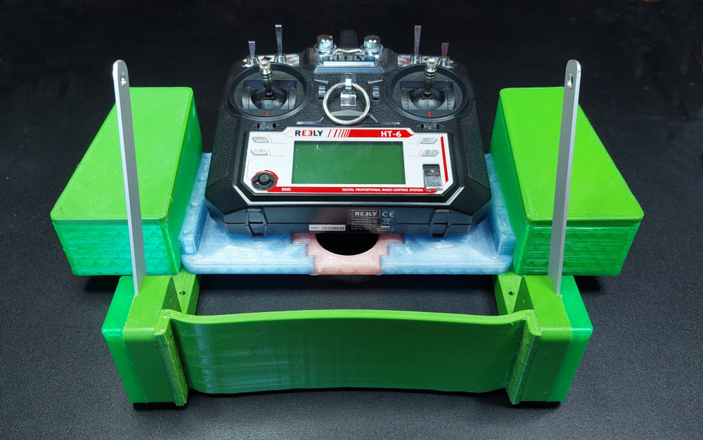
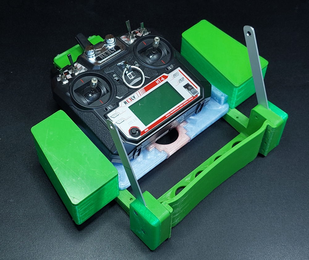
Transmitter console

The transmitter console consists of
several 3D printed parts that are glued
together with epoxy resin.
It is made to be used with a
variety of handheld transmitters. With an
optional extension, the console can be adapted to different
transmitter shapes and sizes.
n
addition to the 3D printed parts, you also need two aluminum
rods, round magnets and some screws.
The individual parts should be printed from PETG, which has
significantly higher thermal stability than
PLA.
When designing and printing the parts for my RC flight models, I
use PrusaSlicer, which can be
downloaded from https://www.prusa3d.de/prusaslicer/,
to realize special desired properties
for 3D printed parts. These properties (e.g. adhesive surfaces
or internal support structures) cannot be
achieved at all or only with great difficulty using a CAD
program alone.
I use modifiers in
Prusaslicer, which are essential for building this glider. For
this reason I do not provide stl-files,
but 3mf-files for download. If you still need stl files,
here (Video: Extract
stl-files out of 3mf-files) you will find a link on how
stl files can be exported in
PrusaSlicer.
The print files can be downloaded on Printables.com:
https://www.printables.com/de/model/286916-little-acro
On YouTube I have published a step-by-step build video of the transmitter console:
Materials needed
- Filament: PETG ca. 450 Gramm
- Aluminium rods: 160 mm x 15 mm x 2 mm (lxwxt): 2 pieces
- Screws M4: Length 16 mm: 16 pieces
- Magnets: Diameter 6 mm, height: 2 mm: 8 pieces
Preparations for assembly
After printing the individual parts, they must be deburred.
All adhesive surfaces must be roughened
with 80 or 120 grit sandpaper. This is important for parts made
of PETG, otherwise the glue joints will
not be stable!
The parts must be glued with 5-minute epoxy resin. Superglue is too brittle for this application!
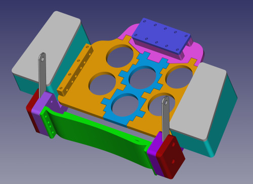
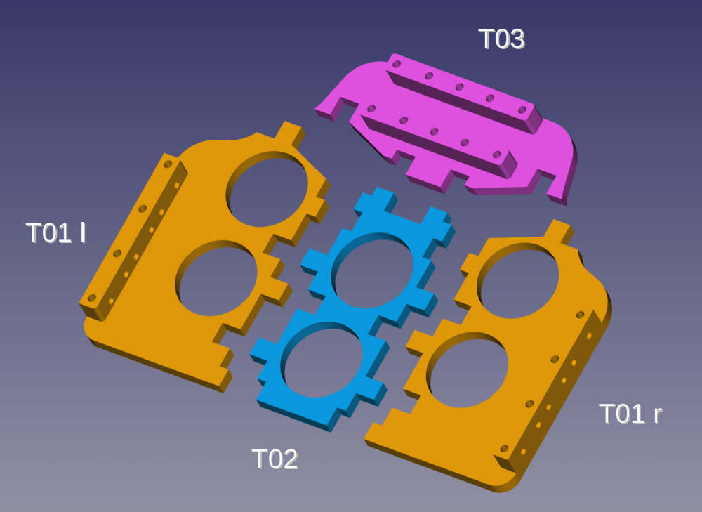
Step 1: Building the base plate
The base plate is made of four parts that are glued with epoxy resin.
Allow the glue joints of the pieces to cure on a flat
surface.
A surface (e.g. laminating film) to
which the epoxy resin does not stick is helpful.
Step 2: Side parts
The two side parts are glued on with epoxy resin.
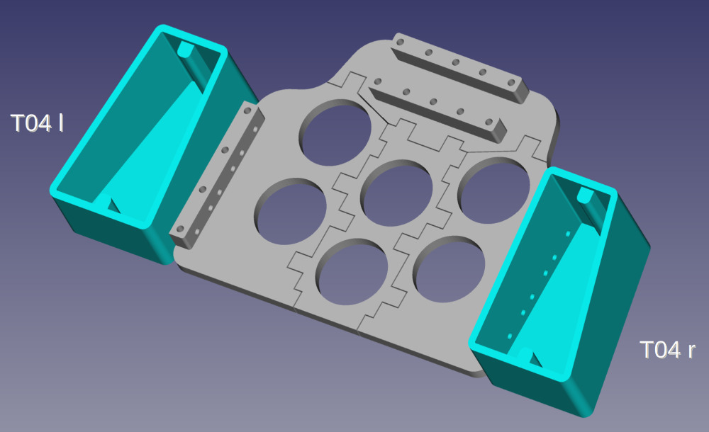
Align the pieces on a flat surface. The holes act as a guide.
Step 3: Bracket
The bracket is made of three parts that are glued together with epoxy resin.
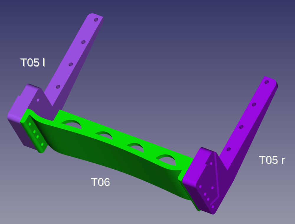
Use a sufficient amount of epoxy resin for the adhesive
surfaces, as the parts are essential for the
stability of the transmitter console.
Align the pieces on a
flat surface. Use clamps to hold the
parts in place while the resin is curing.
Step 4: Connecting the base plate to the bracket
The bracket and the base plate are glued with sufficient epoxy
resin.
Make sure to align the base
plate to match the size of your transmitter.
Before gluing,
take measurements with your transmitter.
If necessary, use the optional extension (parts T11 and
T12).
You must be able to
operate the transmitter sticks and switches well and
comfortably. The aluminum rods that run angled to
the front must not be in the way.
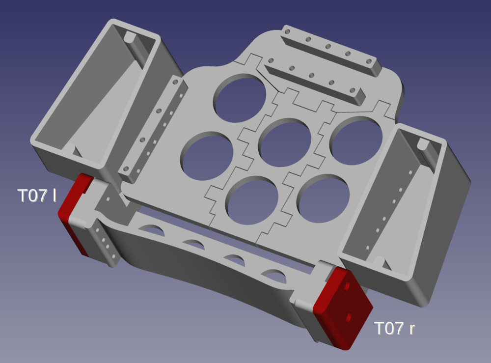
Once the adhesive point has hardened, glue the side parts T07 to the side of the bracket. You can use superglue for this, as the bracket and aluminum rods will be connected with screws.
Step 5: Aluminum support rods
The aluminium support rods are made from a
15 x⊟2 mm aluminium bar.
The length of
the rods can be adjusted to your own preferences. It is between
130 and 200 mm.
The aluminium
rods are rounded at one end. A hole for the neck strap (6 bis
8 mm diameter) is drilled at the
rounded edge.
Slide the rods into the sides of the bracket so you can
pre-drill the holes for the mounting screws with
a 3,5 mm drill bit. However, do not drill completely
through the aluminum rods.
Remove the
aluminum rods and drill the holes at the marked locations to
5 mm diameter.
Put the finished drilled rods back into the sides of the
bracket
Do not glue the rods in place!
The rods are
screwed to the bracket wirht
M4 x 16 mm screws.
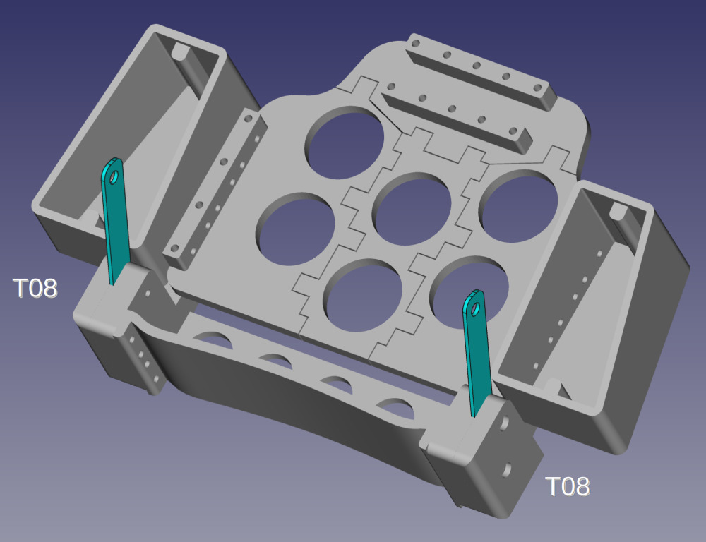
Step 6: Attach the transmitter and side covers
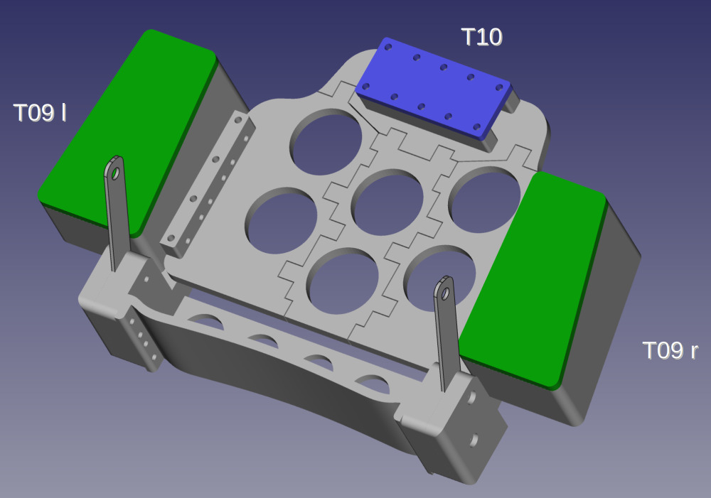
Now attach the transmitter on the base plate. Secure the holding bracket of the transmitter with the holding plate T10. The holding plate is screwed tight with M4 x 16 mm screws.
The lids T09 for the side panels are fixed with magnets. The magnets are glued with superglue to the lid and the inside of the side panels.
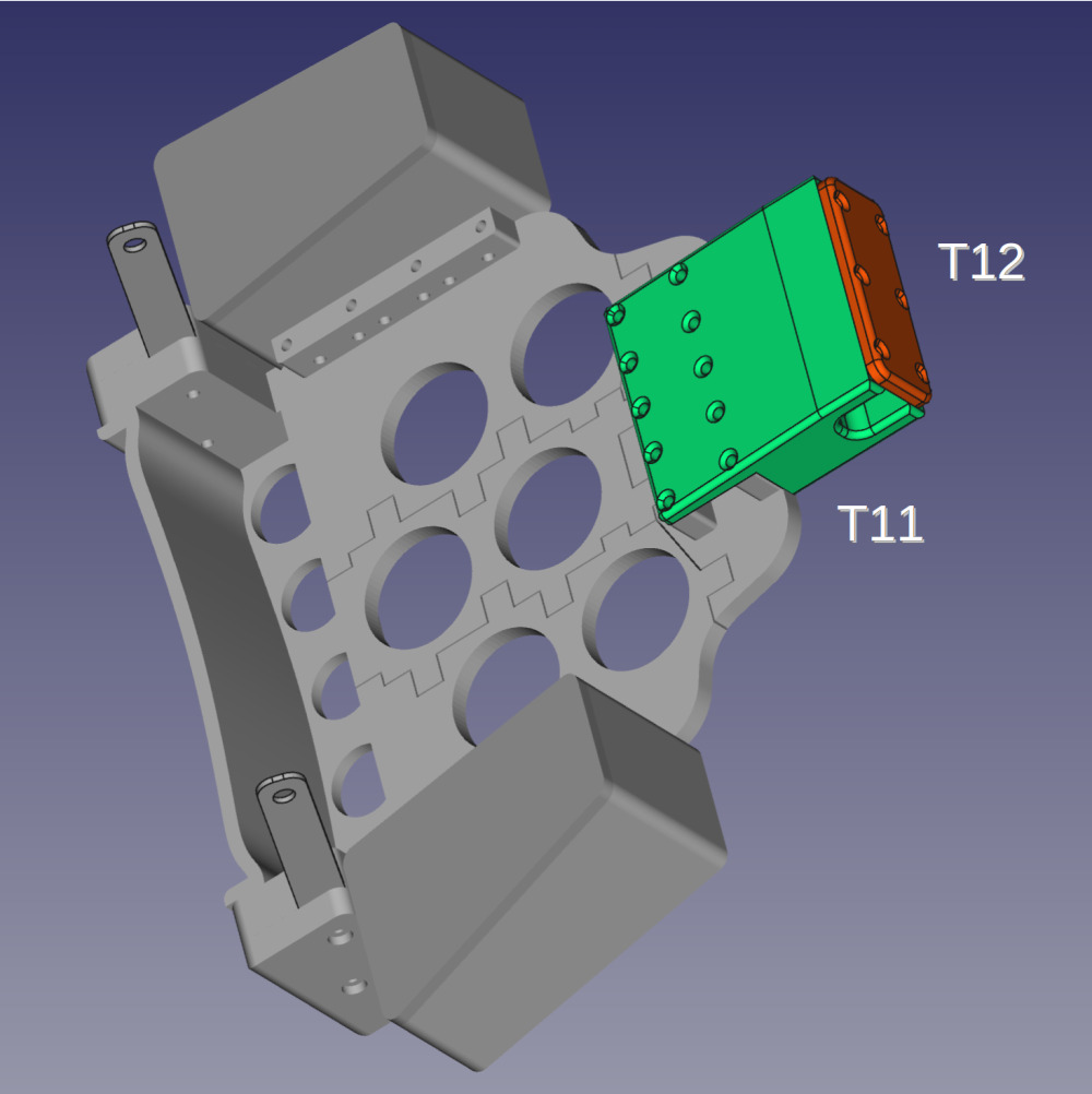
Optional: Extension of the base plate
If the base plate is too short for the transmitter, you can use the base plate extension (parts T11 and T12).
Pictures